
Watermark: Fire Safety Academy logo icon, 70 px, 45 % opacity |
m Remove source references from file description |
||
| Line 1: | Line 1: | ||
== Summary == | == Summary == | ||
A natural-draft gas venting system: flue gas and dilution air rise through the draft hood, connector and Type B vent; if the draft fails, the hood lets the gases spill into the room | A natural-draft gas venting system: flue gas and dilution air rise through the draft hood, connector and Type B vent; if the draft fails, the hood lets the gases spill into the room. | ||
Original illustration for [[Gas appliance venting]]. | Original illustration for [[Gas appliance venting]]. | ||


Latest revision as of 09:07, 13 November 2026
Summary
A natural-draft gas venting system: flue gas and dilution air rise through the draft hood, connector and Type B vent; if the draft fails, the hood lets the gases spill into the room.
Original illustration for Gas appliance venting.
- Alt text: Section through a gas furnace with draft hood, vent connector and Type B vent rising through a roof, with flue gas, dilution air and spill paths
Licensing
New drawing by Fire Safety Academy. © Fire Safety Academy.
File history
Click on a date/time to view the file as it appeared at that time.
| Date/Time | Thumbnail | Dimensions | User | Comment | |
|---|---|---|---|---|---|
| current | 13:07, 12 November 2026 | 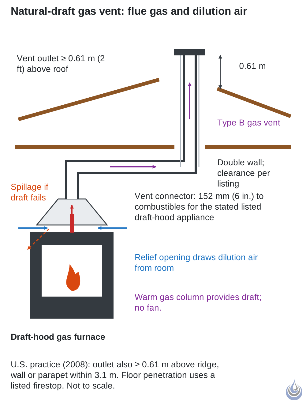 | 1,000 × 1,320 (8 KB) | Peter (talk | contribs) | Watermark: Fire Safety Academy logo icon, 70 px, 45 % opacity |
You cannot overwrite this file.
File usage
The following page uses this file:
