
Contents
Fse-network-model-v1.svg (SVG file, nominally 900 × 600 pixels, file size: 9 KB)
Summary
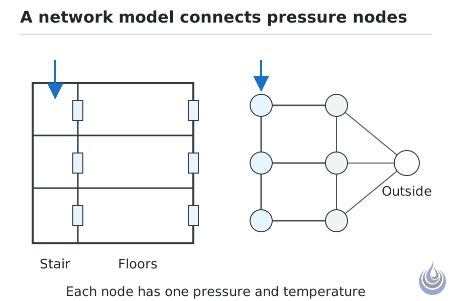
A building section (left) and the same building as a network of nodes and flow paths (right). Based on Klote (2002), p. 4-290, and Ferreira and Strege (2005), pp. 129–130.
Original illustration for Network model, level 4 Expert.
- Source basis: Klote (2002), p. 4-290 (nodes at a specific pressure and temperature, stairwells as a vertical series of spaces, flow from high to low pressure through leakage paths, pressurisation and exhaust); Ferreira and Strege (2005), pp. 129–130 (zones need correct interconnections; shape and size unimportant)
- Alt text: Left: section of a three-storey building with a stairwell. Right: the same building as circles for spaces joined by lines for flow paths.
Licensing
New drawing by Fire Safety Academy. © Fire Safety Academy.
File history
Click on a date/time to view the file as it appeared at that time.
| Date/Time | Thumbnail | Dimensions | User | Comment | |
|---|---|---|---|---|---|
| current | 17:37, 2 November 2026 | | 900 × 600 (9 KB) | Jan (talk | contribs) | Watermark: Fire Safety Academy logo icon, 70 px, 45 % opacity |
You cannot overwrite this file.
File usage
The following page uses this file:
